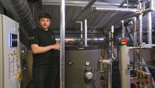
When people talk about heat pumps, the conversation usually starts and ends with hardware: pipework design, compressor efficiency, and refrigerant choice. But in reality, one of the biggest factors that determines whether a system performs well in the field isn’t mechanical at all. It’s how the system is controlled.
At Clade, we see time and again that even the best-designed heat pump won’t perform efficiently or reliably if the controls aren’t properly considered. Control strategy determines how the whole system interacts, responds, and adapts to changing demand, and a solid control strategy is where real-world performance is won or lost.
Understanding the Three Layers of Control
A commercial heat pump system isn’t governed by one controller. It operates across three interconnected layers, each with a distinct role.
1. Unit Controller (Refrigeration Level)
This is the onboard controller managing the refrigeration cycle: compressor speed, expansion valve, defrost, safety protections, and refrigerant envelope.
It ensures the heat pump itself operates safely and efficiently, but it does not manage the wider heating system.
2. Multiplex Controller
This is the core of Clade’s control architecture and the most important part of any installation.
The Multiplex controller manages:
- Temperature differential (ΔT) stability
- Primary flow/return control
- Pump speed and sequencing
- Buffer charging and discharging
- Multiple heat pump coordination
- Night setback and noise-compliance logic
- Protection of refrigerant conditions through return-temperature control
This is where efficiency is won or lost. This is also the layer most often missing or misconfigured in retrofit projects.
3. The Building Management System (BMS)
The BMS manages the secondary side and distributes heat based on occupancy, schedules, and room demands.
Critically, the BMS should not attempt to override or micromanage the heat pump.
Its job is to request heat, not to decide how the heat pump produces it.
When these three layers are aligned, the system is stable, responsive, and efficient. When they aren’t, the system spends its life fighting itself.
Why Controls Are Often Overlooked
In many projects, control design is treated as an afterthought. The focus is on pipework layouts, equipment specification, or hydraulic design, while control logic gets left to commissioning. The problem is that by that point, the system’s limitations are already baked in.
We frequently see issues like:
- Missing sensors
- Incorrect sequencing
- Poor ΔT management
- Primary and secondary pumps fighting each other
- BMS over-control
- Heat pumps being forced into high-return conditions
That’s why our design process at Clade gives controls the same attention as any other part of the system. They’re not optional extras; they’re integral to how the system functions day-to-day.
Designing for Retrofit
Most of Clade’s current projects are retrofits. That means integrating new low-carbon heat pumps into existing building systems that were never designed for them. In this context, controls are often the key to making a retrofit feasible without tearing everything out.
By matching heat pump flow and return temperatures to existing systems, we can simplify control logic and retain much of the secondary-side infrastructure. This reduces costs, minimises downtime, and makes it easier to deliver measurable carbon savings quickly.
Hybrid systems are another area where intelligent control makes all the difference. In these cases, heat pumps handle the base load, while existing boilers cover short-term peaks. With the right sequencing and predictive logic, this combination delivers lower running costs and lower emissions without compromising resilience.
Clade’s Control Philosophy
One of the largest differences between boiler sequencing and heat pump sequencing is how the system is stabilised.
Clade systems use:
- Fixed return temperature control
- Floating flow temperature
- Stable ΔT (typically 10–25°C depending on refrigerant)
- Primary pump modulation through PICVs and pressure-independent control
Controlling on return temperature stabilises the refrigerant cycle and prevents the oscillations that lead to poor efficiency, short-cycling, and excessive compressor wear.
This principle is embedded in our Multiplex controller. It’s also why we pay such close attention to emitter performance, buffer sizing, pump selection, and BMS integration during design.
Why Clade Integrates Controls from Day One
Because we design, manufacture, install, and maintain our own systems our controls are designed into the architecture.
From feasibility through to construction and aftercare, our team ensures the control strategy matches:
- Site heat profile
- ΔT expectations
- BMS configuration
- Pumping arrangements
- Noise requirements
- Electrical limitations
- Refrigerant characteristics
This holistic approach is why Clade systems deliver real site performance.
Talk To Us About Heat Pump Controls
Getting the controls right is what makes the difference between a heat pump system that just runs, and one that performs at its best for years to come. From schematic design and sequencing logic to commissioning and fine-tuning, every stage of control design plays a role in efficiency, reliability, and long-term performance.
But it’s not something you need to be concerned about.
You can leave that to our experienced team of engineers here at Clade, who will support you from system design and installation all the way through to commissioning, monitoring, and optimisation.
With over 35 years of experience working with natural refrigerant heat pumps and integrated control systems, we know what it takes to deliver consistent, efficient, and reliable heating performance, from day one and for the long term.
Just get in touch to discuss your next project or find out how we can help you optimise your system controls.
]]>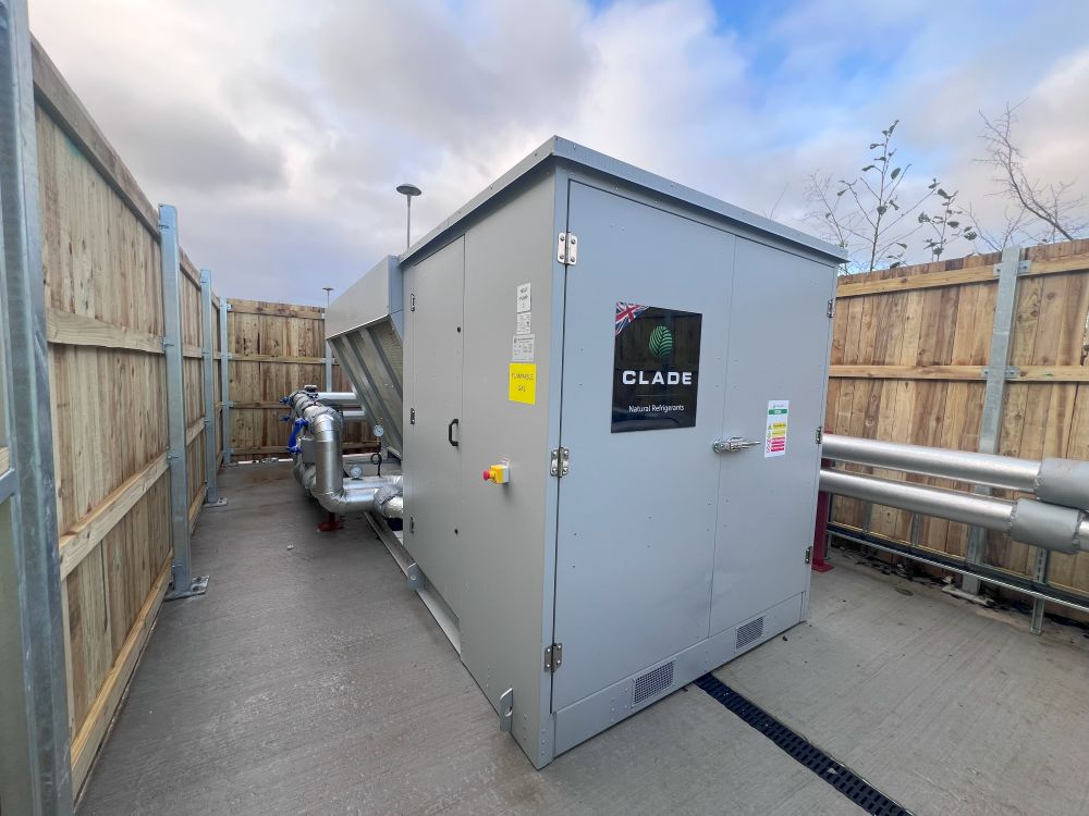
At Clade, we’ve always been at the front of the curve when it comes to manufacturing, designing and installing R290 (propane) heat pump systems.
Just a year ago, we were one of the only suppliers of R290 heat pumps. But now, there are many suppliers available – and for good reason!
R290 refrigerant gas is incredibly high-performing and has excellent environmental credentials with an incredibly low global warming potential (GWP).
With that in mind, I thought it time to share the principles of R290 system design, and to take a look at some of the key considerations that need to be accounted for when working with this refrigerant.
Here’s all you need to know.
What are the principles of R290 schematic design?
The principles of R290 schematic design are very similar to those of CO2 schematic design, which I’ve written about previously.
A schematic is essentially a full drawing of how all the pipework in a building connects, showing the entire building on one piece of paper.
This includes all emitters, heat pump units, buffer vessels, valves, and more.
Just like CO2 systems, a Clade R290 system will usually require…
- A buffer vessel to provide the hydraulic separation between the primary side and secondary side, so that both can do their jobs without interfering with one another
- Two domestic hot water (DHW) cylinders for DHW production – a hot store vessel and a stratification cylinder
- A building management system (BMS) that can alert building operators to high or low return temperatures, so any issues can be resolved before they cause the heat pump to turn off
- Proper controls to maintain the Delta T (the difference between the flow and return temperatures)
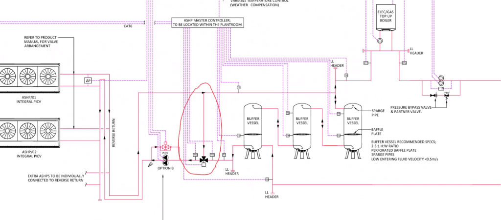
There’s only one visible difference between a Clade CO2 schematic and a Clade R290 schematic: a Clade R290 system requires three-port back-end protection valves.
R290 and three-port back-end protection valves
When we’re designing an R290 system – or looking at a third-party design for a Clade R290 heat pump – we look for a three-port back-end protection valve.
That’s the section circled in red on this example R290 schematic.
Why do we need three-port back-end protection valves?
Three-port back-end protection valves are important on our R290 systems because R290 has a much smaller Delta T than CO2.
With CO2, we design for a 30C return temperature. But with R290, we design for a 60C flow and a 50C return (although our high-temperature Elm and Yew heat pumps are slightly different).
This gives us a 10C Delta T, which makes for conditions much more similar to those used by traditional gas boilers.
The benefit is that it makes retrofitting R290 particularly straightforward. But it also means the need for bigger pipework and, of course, three-port back-end protection valves!
It’s worth noting that a three-port back-end protection valve isn’t always necessary, as it will also depend on peak load and kilowatt delivery.
However, if you’ve got a kilowatt imbalance (for instance, you’re using buffer vessels as a load) then a three-port back-end protection valve is a must.
What does a three-port back-end protection valve do?
The job of the three-port back-end protection valve is to work continuously to maintain the desired return temperature to the heat pump.
Clade commercial heat pumps work based on a controls philosophy that requires a consistent Delta T.
So, let’s imagine for a minute that your return temperature drops to 45C from the desired 50C.
This would ordinarily cause your flow temperature to drop too – so, you’d end up with a 55C flow temperature instead of 60C. Not ideal!
That’s where your three-port back-end protection valve comes in.
This valve will maintain your heat pump return temperature so that it’s always 10C below your desired flow temperature – therefore maintaining the flow temperature.
It does this by mixing some of the warmer flow with the cooler return, to get to that desired return temperature and keep that Delta T exactly where it should be.
The principles of DHW production on an R290 system
If you’re hoping to produce both space heating and DHW with your air source heat pump, there is another key difference between CO2 and R290 systems.
Essentially, with CO2, you can easily produce DHW at 60C through a plate exchanger.
This is because CO2 typically operates at high temperatures.
On the other hand, most R290 systems (discounting our high-temperature Elm and Yew units) will struggle to produce a guaranteed 60C hot water supply without a bit of help.
This is because the maximum flow temperature they can generally reach is 65C, and then you’ll typically experience losses getting to the plate and crossing it – meaning you could easily end up with a 59C DHW supply instead of 60C.
Yes, it’s very close. But it’s not compliant.
That’s why, when it comes to R290 systems, we typically use an electric boiler to top up the temperature of DHW after it’s heated up by the plate exchanger.
So, if we’re left with a 59C supply of hot water after crossing the plate exchanger, the electric boiler will top the temperature up to 60C to make sure it’s compliant.
This way, you get a guaranteed, compliant DHW supply while keeping just one system for space heating and DHW.
It does involve paying to run an electric boiler. But because the heat pump is doing the majority of the work, this is still much more efficient – and cost-effective – than running a gas boiler.
It’s also ideal for retrofit projects, as you’ll be able to benefit from the fact that R290 requires fewer secondary side changes while still enjoying an efficient (and low carbon) DHW supply. Which brings us onto…
Minimising secondary side changes
The great thing about an R290 system is that the Delta T closely matches the Delta T of a traditional boiler.
This means you can often get away with making fewer changes to the secondary side – which tends to be a priority for retrofit clients.
After all, it keeps costs down, minimises disruption, and allows for continuous operation.
Often with an R290 system, you’ll be able to retain pipework, valves and more – simply switching out the emitters for larger ones (although if a building’s emitters were previously oversized, sometimes even this won’t be necessary).
In fact, our high-temperature Elm and Yew R290 heat pumps can work as direct boiler replacements, and are designed especially for buildings where changes can’t easily be made to a building’s infrastructure – like listed buildings and hospitals.
In this way, when it comes to retrofitting a heat pump, there’s less design velocity that has to go into an R290 system compared to a CO2 system.
Weather compensation
Another benefit of R290 is the ability to weather compensate.
This can drastically improve your heat pump’s efficiency and therefore lower your heating bills even more.
Essentially, when it comes to R290, Delta T is the priority – in contrast to CO2, which is dependent on maintaining a set return temperature.
This means that, when ambient temperatures are -5C, you could have a flow and return of 80-70.
Meanwhile, if ambient temperatures climb to 5C, you could adjust the flow and return to 50-40 to drastically improve your heat pump’s COP.
Better still, many buildings already have weather compensation built in, so tagging propane onto these existing systems is generally quite easy– another reason why R290 is easier to retrofit!
Safety considerations for R290
Unlike CO2, R290 is flammable.
This means there are some key safety requirements that we have to establish as a manufacturer – although the regulations around it are still quite vague.
Our blog on R290 and flammability goes into a lot more detail. But here are some key safety measures we prioritise here at Clade.
Degasser
A degasser isn’t a legal requirement. But at Clade, we like to be standard setters in the industry and always recommend a degasser for our R290 heat pump systems.
This safety device would mitigate any damage to your system and ensure the safety of everyone inside the building in the very unlikely event that your plate heat exchanger fails and allows propane to leak into the heating system itself.
Safety valves
Like all heat pump systems, R290 systems require safety valves.
If there’s a fault and temperatures start rising, these release pressure in the system so that the pipework doesn’t burst.
ATEX zone
All R290 heat pump units have an ATEX zone, which is basically an area above the heat pump where you can’t put anything that might catch fire.
This is in case there’s a pressure fault in the system that causes the safety valve to expel any pressure and gas.
Location
At Clade, we also advise designers to be mindful of what’s around the unit, even when it’s not in operation. After all, there’s always a chance that there’s a fault that causes propane to leak to the side of the unit when it isn’t running.
That’s why we suggest designers always do a DSEAR assessment (a kind of on-site safety assessment) to ensure R290 units are being positioned somewhere suitable, away from potential sources of ignition.
Talk to us about R290 systems
As you can see, there are lots of things to take into account when designing an R290 heat pump system.
But they also require a lot less work than CO2 heat pumps when it comes to retrofit projects. Plus, when you get the design right, the rewards are many.
Building owners can benefit from an efficient, low-carbon and safe heating system that’s easy to retrofit and even allows for weather compensation.
At Clade, we’ve been at the front of the curve when it comes to manufacturing, designing and installing R290 heat pump systems for years. So, you’re in safe hands!
Simply get in touch to find out more and get your project started.
]]>
CO2 (also known as R744) is a highly efficient, non-corrosive and non-toxic natural refrigerant.
This makes it an excellent choice for heat pump systems. Which is why we’ve been at the front of the curve, designing, manufacturing and installing CO2 heat pump systems for years here at Clade!
Here, I’ll walk you through the principles of schematic design for CO2 heat pump systems and introduce you to the main considerations that need to be taken into account when designing a system that contains this refrigerant.
But first…
What is a schematic design?
In simple terms, a schematic is a blueprint of the fluid system.
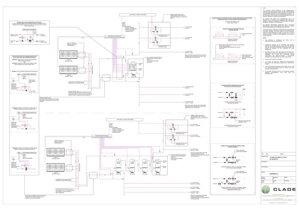
It’s essentially a full drawing of how all the pipework in a building connects, showing the entire building on one piece of paper. This includes all emitters, heat pump units, buffer vessels, valves and more.
By starting with a schematic, we’re able to figure out how the fluid system in a building will work and be controlled, which is a vital part of the design process.
Achieving a 30C return
With CO2 heat pump systems, we design for a 30C return temperature.
By return temperature, we’re referring to the temperature at which water returns to your heat pump after circulating through the heating system.
Why design for a 30C return?
30C is the optimal return temperature for maximising a CO2 heat pump’s efficiency (leading to lower energy consumption and reduced operational costs).
This is essentially due to the refrigerant’s unique properties – and the fact that we need a return temperature that’s within the envelope operating temperature of CO2 to get out of the transcritical state that’s been achieved using compression from the compressor.
30C is also well below our maximum current return temperature for CO2, which is 38C.
This gives our systems some wiggle room before the return temperature reaches a figure that would cause the heat pump to turn off.
How do we achieve a 30C return?
Achieving a 30C return is all about emitter design and controls.
A schematic shows all your valves and how these are controlled – for instance via a Building Management System (BMS) or master controller system.
Below are diagrams of the emitters that the industry uses 95% of the time:
- Radiators
- Air handling unit coils, heater batteries or fan coil units
- Radiant panels
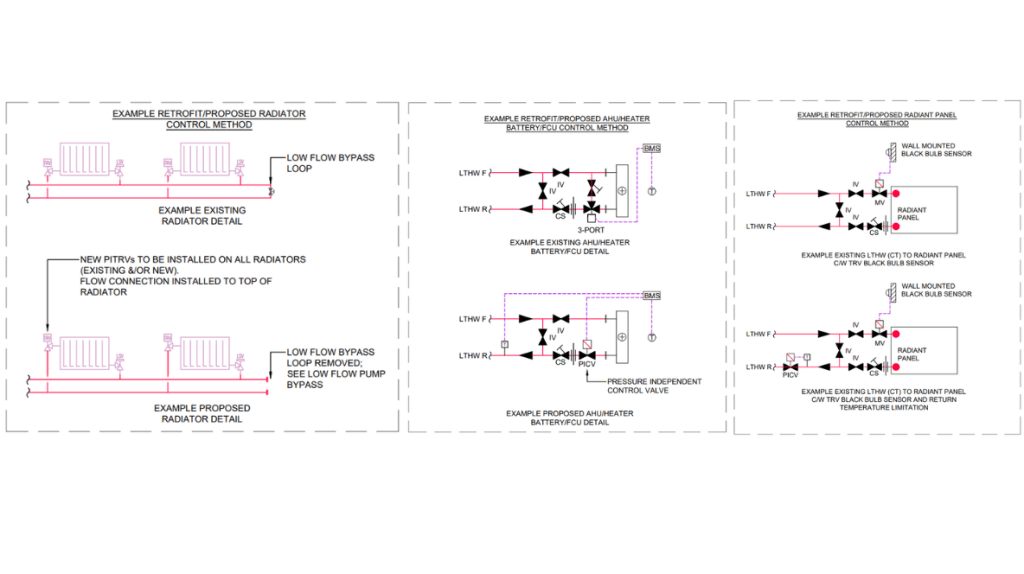
These diagrams essentially show that, to achieve a 30C return, all you need to do is have two-port constant temperature variable volume control, and then also, as a backup, look at the return temperature coming off the emitter.
In other words, you control the flow rate through the emitter on your off temperature (meaning the room’s temperature set point). Then, at the same time, you monitor the return temperature coming off the emitter and limit this so that it doesn’t go beyond the accepted range of the CO2 air source heat pump system.
You can get much more detail on the role of control valves and emitter design over on our dedicated blogs.
The importance of control
Taking proper control of emitters isn’t a new concept.
Two-port control is a part of standard building services, and we’ve been doing it for decades here at Clade.
Perhaps more importantly, all heating systems can benefit from it and should be using it. Even with a boiler, achieving the right return temperature will optimise its efficiency.
So, why are many contractors uninformed and inexperienced in this area?
Well, the return temperature doesn’t make quite as big of a difference in boilers as it does in natural refrigerant heat pumps. So, contractors have historically gotten away without putting these control valves in, which is cheaper.
However, it’s not rocket science.
Two-port control is simply about slowing the flow rate down. Yes, it’s more expensive than going without. But it’s absolutely worth it to achieve better operation control and efficiencies on any system – boilers, CO2 heat pumps and propane heat pumps alike.
Achieving separation between primary and secondary
Heating systems all have a primary side and a secondary side.
The primary side is your heat generation. So, for instance, you could have an air source heat pump or a boiler doing your primary loop.
Meanwhile, the secondary side is the loop that goes out to the emitters in your building and back.
These two loops need to be separated in some way.
On boiler systems, this can be achieved using a low loss header, which is essentially a really big pipe. Your boiler feeds into the top of it and pulls from the bottom, while your system side pulls from the top and feeds back into the bottom.
When it comes to air source heat pumps, we use the same philosophy. But instead of a big pipe, we use a buffer vessel.
The air source heat pump flows into the top of the buffer vessel and pulls from the bottom, while the secondary side pulls heat from the top and puts the cold return fluid into the bottom.
In this way, the buffer acts as the hydraulic separation between the primary side and secondary side and allows both to do their jobs without interfering with one another.
Dealing with domestic hot water production (DHW)
One of the myths that you might hear about heat pumps is that they’re not reliable at domestic hot water production (DHW).
However, this is simply not true!
At Clade, our CO2 heat pumps have proven repeatedly that they can consistently produce a hot water supply – both at 60C, and even up to 80C.
So, how do we achieve this while maintaining a low 30C return temperature? Here are the key considerations.
1. The ‘on’ temperature
Firstly, the ‘on’ temperature of the water that you’re raising has to be lower than the 30C low temperature hot water return off the primary side of the plate heat exchanger.
So, as an example, if the temperature going on to a plate exchanger is 10C, this can easily be raised to 60C using a 70-30 system.
On the other hand, if the temperature in your DHW cylinder happened to be 50C, you wouldn’t be able to raise this to 60C using a 70-30 system. This is because, on the low temperature hot water primary side return, you’d be coming off at 55C (which is higher than 30C).
2. Domestic hot water cylinders
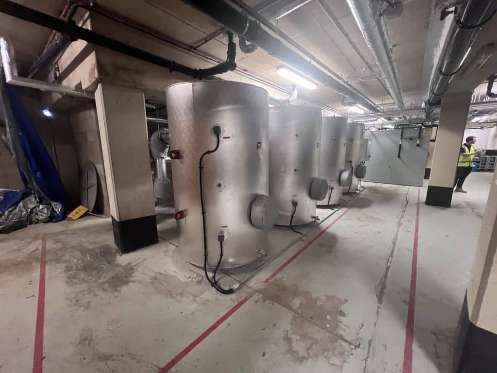
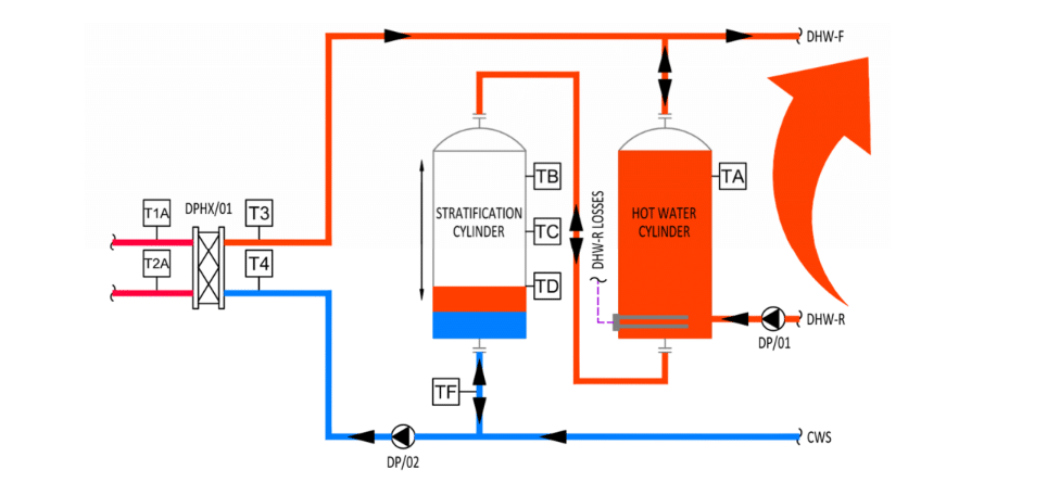
When it comes to DHW, we have two cylinders.
One is maintained hot at all times (the hot store vessel), using direct electrical immersions to cover your domestic or water return losses.
The other is known as your stratification cylinder.
When people turn on the taps in your building, the cold return water gets fed into the bottom of this stratification cylinder, which is separated into layers based on temperature (known as stratification).
At the same time, the hot water at the top of the cylinder (which has reached the desired temperature) gets fed into the bottom of the first hot store vessel, ready to go when someone turns a tap back on.
3. Stratification control
The way that we raise that 10C ‘on’ temperature with CO2 is through stratification control.
Essentially, when cold return water first enters the bottom of the stratification cylinder, there’s a point where you’ll have 60C (or your desired temperature) at the top of the vessel and 10C at the bottom.
However, as taps stay on, cold water will continue to come in at the bottom, while hot water will continue to go out of the top.
So, the stratification layer will slowly move up the vessel, and you’ll eventually end up with the whole cylinder at 10C (while your hot store vessel is still fully hot).
At this point, it’s time to turn on your DHW production and use your plate heat exchanger to raise the temperature of the cylinder from 10C to your desired temperature.
In this way, it’s possible to maintain that 70-30 flow/return on the primary side.
We have a Clade domestic hot water controller available which will monitor and control all the DHW stratification control requirements.
This controller also goes through a destratification programme once an evening as a minimum to maintain all cylinders above 60C for 1 hour in 24.
What happens when my return temperature goes up?
If your return temperature climbs above a certain figure (38C for Clade CO2 heat pumps), your air source heat pump will turn off.
So, it’s important to have a building management system (BMS) in place that will monitor your emitters and flag a rise in return temperatures.
Raised return temperatures can happen for two reasons:
- You haven’t got proper control of a secondary system
- Faulty equipment (eg. a faulty valve, faulty cable, or faulty fan in an air handling unit)
A BMS won’t just flag high return temperatures. It can also tell you which part of the system is causing the problem (whether it’s an emitter, fan coil or air handling unit) so that you can easily carry out some maintenance to correct the issue.
Better still, you can programme a BMS with high-level limits and alarms so that, if return temperatures do start climbing, you can hopefully resolve the issue before it gets to a stage where the heat pump would turn off.
At Clade, our innovative Master Controller optimises performance across your whole heat pump system and empowers operators with clear, actionable insights. So, you can ensure that your system is extremely reliable.
Refrigerant safety
As it’s non-flammable and non-toxic, CO2 is classified as a safety group A1 refrigerant – the safest class available!
However, it does run at a very high pressure – around 120 bar. This is about 120 times greater than atmospheric pressure.
It’s what enables CO2 to go into a transcritical state (where it possesses properties of both liquid and gas) and achieve those sought-after high temperatures.
But it can also cause some people to worry about the safety implications of such a high-pressure system.
Rest assured, this isn’t something that you need to be concerned about.
Fully contained
Firstly, all Clade CO2 units are fully contained in compressor housing.
Everything inside these containers is rated at high pressures – including the equipment. And all joints are welded together to ensure they can withstand the pressure.
This means there’s no exposed pipework to worry about.
Testing
We pressure test our units using nitrogen before they get filled with CO2 gas.
Testing takes place within a special pressure test bay within the factory, which has thick, bomb-proof doors.
Every Clade unit is tested and certified before it leaves.
Burst discs
In a low-temperature hot water system, you’d set safety valves (also known as pressure relief valves) to release at around 0.6 to 0.9 bar above normal operating pressures.
The role of a safety valve is to release pressure in the system if there’s a fault and temperatures start rising, so that pipework doesn’t burst.
When it comes to CO2 systems, however, we use bursting discs as well. This is because CO2 runs at such high pressures.
Essentially, if the plate heat exchanger that sits between the refrigerant and the low-temperature hot water ever ruptures, you’ll have a sudden increase in pressure in a part of the system that isn’t rated for it.
Your bursting disc has a larger diameter than a safety valve and is designed to completely rupture if there’s a sudden pressure increase, to instantly release the high pressure.
We still use safety valves for normal fluctuations. But the addition of a bursting disc means our systems are still incredibly safe if, for whatever reason, there’s a catastrophic failure where the CO2 enters the rest of the system.
Talk to us about CO2 systems
As you can see, CO2 heat pump systems are a fantastic way of generating both space heating and DHW safely, efficiently and without harming the environment.
And creating a schematic design is an essential step in making sure your system is working for your building and its inhabitants, rather than against them.
At Clade, we have over 35 years of experience working with natural refrigerants like CO2. So, we know what we’re doing when it comes to designing, manufacturing, installing and maintaining these systems.
In fact, if you’re interested in swapping your commercial boiler for a natural refrigerant heat pump, we may just be the safest pair of hands there is!
Get in touch with our team to learn more and to start the ball rolling on your project.
]]>
Whether at home or at work, keeping warm is essential. But commercial heating systems are very different from residential ones.
Not only do they need to heat a larger space, but they also have different requirements to account for.
For instance, they might need to support activities like cooking and drying for industrial processes. And they may need to cater for several different offices or departments that each have different heating needs.
Here, we’ll break down the different systems typically used for commercial heating and cooling – and the various considerations you should keep in mind.
Types of commercial heating systems
Here are five key types of commercial heating.
Hydronic or water system heating
Heat is generated by a central source, transferred to a distribution system that uses water to carry heat to emitters in each room or area.
This is one of the most common heating systems in the UK. In commercial heating systems, there are often a variety of types of emitter including; fan coil units, radiators, underfloor, air handling units, unit heaters, trench heaters etc. Each has specific requirements for the supply and control of heating.
There are a variety of heat sources that can be used, these are described below.
Direct warm air space heating
Warm air space heating systems are also known as heat exchanger systems.
They use a fan to pass air over a heat exchanger, in order to warm it up and distribute it evenly through a space.
In this way, warm air space heating is ideal for commercial settings where a constant temperature is needed throughout the building.
The heaters themselves can be wall-mounted, freestanding or even suspended in the ceiling above the space being heated. There are several version of this:
Destratification heating
Destratification heating systems use destratification fans to mix the air inside a building.
Essentially, this all comes down to the fact that heat rises – making it hard to heat the floor level of buildings that have very high ceilings.
Usually combined with warm air heating, destratification heating systems are able to recirculate warm air so that the temperature is consistent across a whole room and warm air doesn’t just sit in the ceiling or roof area.
Air rotation heating
Air rotation heating systems constantly draw in cool air from below the heater to warm it up before it’s recirculated.
This has the effect of destratification, meaning it’s a great way to create an even temperature without the need for destratification fans.
These systems are also powerful enough that, in most cases, a single heater can provide consistent heat across a whole room – so, you won’t need expensive ductwork to direct heat around a building.
Air rotation heating is especially useful for settings that require constant background temperatures or frost protection as the consistent temperatures generated remove the risk of condensation.
Radiant heating or direct electric heating
Radiant heating systems emit heat energy from the hot surfaces of electric heaters.
In large commercial settings, radiant heating is often provided by radiant tubes or radiant plaque heaters, which are suspended from a ceiling.
These emit infrared radiation, meaning they can heat the people and objects exposed to them without directly warming the air. These people and objects then act as secondary heaters, helping to raise the temperature even further.
Types of commercial heating sources
So, now you’re familiar with the various ways that commercial heating systems can be used to distribute heat around a room or building.
But what about the heating source itself?
Commercial boilers
Most commercial buildings are heated using commercial boilers.
These can be oil or gas, but gas is most common. In fact, in the non-residential sector, two thirds of all space heating uses natural gas.
Whichever fuel is used, a commercial boiler works by passing water over a series of flames to warm it up. This is then sent to your emitters to distribute heat through your building – or used to create steam that is sent through your pipe system.
Commercial heat pumps
Commercial heat pumps are growing in popularity in commercial and industrial settings, thanks to their ability to produce zero emissions – as well as their economic advantages.
Air source heat pumps extract warmth from the air outside, which causes a refrigerant to evaporate and turn into gas. This is then moved through a compressor to raise the temperature using a small amount of electricity, before it’s passed over an internal heat exchange surface to warm up the water that heats your commercial building.
Heat pumps are three or four times more efficient than gas boilers and can also help businesses to save money. After all, just 30% of the energy used by an air source heat pump is typically provided by electricity, with the rest being generated for free by the environment.
The environmental heat can be taken from the air, water or ground.
Air source heat pumps
These are easy to fit and are generally positioned on a roof or in an open space near the building. Heat is absorbed from the surrounding air and therefore efficiency varies with air temperature.
Water source heat pumps
The water can be in lakes, mines, rivers, underground aquifers, waste heat, just about anywhere. Water is pumped through the evaporator heat exchanger to transfer heat to the refrigerant. The water can be direct or indirectly piped to the heat pump depending on the quality of it, e.g. dirty water can block the evaporator heat exchanger and should have separation to prevent this happening.
Ground source heat pumps
The ground is warmed by the sun, this heat disperses downwards and is a fairly consistent temperature all year round. A slinky or a bore hole is used with a brine filled pipe to extract the heat, the consistent temperature leads to consistent efficiency. Care has to be taken in the design of the underground array to ensure that too much heat is not extracted.
All types of heat pump have the advantage of being able to be powered by onsite solar and wind turbines, which reduces their cost to run.
As a double bonus, heat pumps can also be operated flexibly – meaning you can make heat when electricity is cheap but use heat when you want. Again, this reduces the cost of heat.
Clade heat pumps have smart connectivity built in, ready for a flexible future.
Choosing your commercial heating and cooling system
There’s no ‘one size fits all’ when it comes to commercial heating.
Rather, the right commercial heating and cooling system will vary depending on your space and requirements. Here are some factors to take into account.
Size of the space to heat
The bigger the size of your space, the more it will cost to heat.
This is true for any heat source or system. Heat pumps can heat any building to any temperature anywhere on the planet.
Consider efficiency measures to reduce heat loss either through the building fabric or ventilation.
Use of the space and heating system
What is your space used for?
Premises used for storage, manufacturing or office space will all have different heating requirements.
Similarly, some commercial businesses will need heat energy for multiple processes, not just space heating – for instance, distilling, drying, cooking and sterilising.
The design of the system and specification of the heat source should suit the use. For example hot water is best generated by a CO2 heat pump, whereas background heat for a warehouse is best from a DX heat pump in an AHU like our Spruce heat pump.
Available space
Consider how much space you have to house your heating system.
To give you an example, biomass boilers require a large amount of space, as you’ll need to be able to store the wood pellets it uses.
Meanwhile, an air source heat pump will need some outdoor space to house the main unit. This could be on a roof or in an open space nearby, typically a car park.
On or off-grid
Many commercial premises in the UK operate in rural locations and don’t have access to mains gas.
If this applies to your business, you won’t be able to use a natural gas fired boiler.
LPG and oil are both options, although you’ll have to deal with fuel deliveries. Meanwhile, a heat pump is a totally off-grid heating system that will cost less to run and avoid carbon emissions.
Energy emissions
If you’re keen to reduce your business’ carbon footprint, a clean heating source like a heat pump will be the best solution.
Opting for a heat pump that uses natural refrigerants – like our commercial heat pumps here at Clade – will reduce your impact on the environment still more.
It’s worth noting that, even if your business’ impact on the environment doesn’t concern you, switching to an emissions-free heating source will help to future-proof your business – preventing your heating system from potentially becoming a stranded asset thanks to tightening environmental regulations.
Talk to us about commercial heating
As you can see, there’s a lot to consider when you’re choosing a commercial heating system for your business.
But don’t worry, you’re in the right place.
Our team of expert engineers has over 35 years of experience working with natural refrigerant commercial heat pumps and refrigeration equipment.
Simply get in touch to learn more about how we can help you achieve a commercial heating system that’s clean, futureproof, efficient and cost-effective to run.
]]>
Your heat pump has to work as a team with your heating system to deliver heat efficiently.
So, it’s super important that your heating system is designed specifically for the heat pump selected. And that includes the emitters!
Here, we’ll cover all you need to know about natural refrigerant heat pumps and emitters – from what types of emitters work best, to the emitter design considerations to bear in mind.
What emitters work best with air source heat pumps?
There’s a common misconception that heat pumps don’t pair well with radiators.
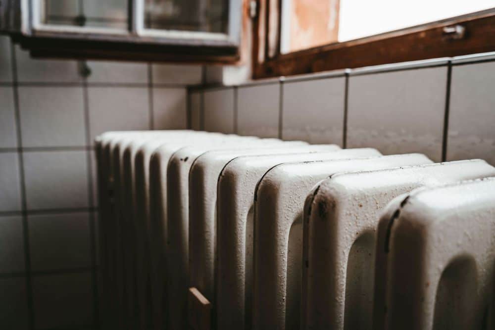
But this isn’t true at all. Just like boilers, heat pumps are very effective when paired with correctly sized radiators.
Just like boilers, the heat emitters have to be matched to the heat pump and its refrigerant.
But unlike boilers, heat pumps are more sensitive and have lower tolerance of poorly sized emitters – see our blog on optimising control.
Can you keep your existing emitters when you retrofit a heat pump?
Most of the time, you’ll need to replace your emitters with different ones if you’re switching from a boiler to a heat pump.
This is because, as we’ve touched upon already, heat pumps operate at different flow temperatures and different temperature differentials (DTs) – meaning they require a larger surface area to achieve the same heat output.
That said, it isn’t always the case. Whether you need to replace your radiators when retrofitting a heat pump will vary based on factors like:
- Your existing boiler
- Your existing radiators
- Your heat pump and refrigerant
In particular, many buildings in the past have been fitted with oversized radiators – making them suitable for low flow temperatures already.
Likewise, if you can’t easily make changes to your building’s existing infrastructure, your system designer might recommend a high temperature heat pump that’s designed to allow you to keep your building’s existing emitters.
Our Elm heat pump has been designed especially for this purpose, and is the UK’s first direct boiler replacement heat pump.
The importance of temperature differential (DT)
Temperature differential – also known as Delta T or DT – is the difference between the flow and return temperatures.
The flow temperature is the temperature that your heat pump heats your water to before it gets sent to your radiators.
Meanwhile, the return temperature is the temperature at which it returns to your heat pump after flowing through your radiators.
Maintaining the correct DT in a heat system is essential for the operation of any heat pump.
Every refrigerant will have a different optimal DT. However, to give you an example, CO2 (R744) is most efficient with a 70C flow and 30C return.
Yes, some CO2 heat pumps can tolerate higher return temperatures, but the efficiency will be severely affected.
With that in mind, the whole system design for a CO2 heat pump should be predicated on achieving these optimal temperatures.
After all, designing and installing your heat pump system to be as efficient as possible is key to maximising carbon savings and minimising energy costs!
The role of thermostatic radiator valves (TRVs) in maintaining DT
Because refrigerants are so sensitive to flow and return temperatures, standard thermostatic radiator valves (TRVs) aren’t recommended with heat pumps.
Instead, natural refrigerant heat pumps tend to work best with differential pressure (DP) TRVs.
Why?
Well, a system with standard TRVs will create the design DT when operating at full demand (with all TRVs open) – assuming properly sized radiators and design conditions.
But, at partial demand, standard TRVs won’t control flow properly and the return temperature will rise.
On the other hand, DP TRVs won’t allow higher than set flow rates through emitters.
This means they can control flow properly at both full and partial demand to keep the return temperature as designed.
Standard TRVs
To show you what we mean, let’s look at a CO2 heat pump with a flow of 70C.
In this example, lock shield valves provide the balancing and TRV heads provide demand control of rooms – while a constant pressure pump reacts to system pressures.
Here’s what happens when the system operates at full demand with all TRVs open:
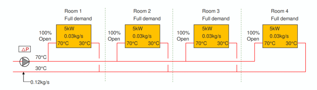
As you can see, with all TRVs open, the return temperature matches the desired 30C.
Now let’s see what happens when the system operates at partial demand, with two TRVs open and two shut:
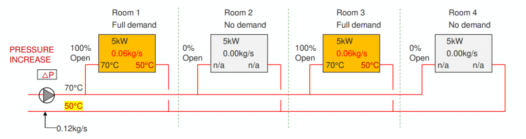
Here, the pressure increase leads to an elevated 50C return temperature – massively compromising the heat pump’s efficiency.
Differential pressure (DP) TRVs
Let’s take a look at that same CO2 heat pump, but switch the standard TRVs for DP TRVs.
Here, the system is again operating at partial demand, with two TRVs open and two shut. But because DP TRVs have been used, the flow is still controlled properly and the return temperature remains as designed:
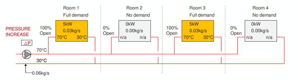
As you can see, despite the pressure increase due to the partial demand, the flow through each of the open TRVs remains at 0.03kg/s – as it would if all four TRVs were open.
In this way, the return temperature is able to remain at 30C – its most efficient – allowing the end user to maximise carbon savings and reduce energy costs.
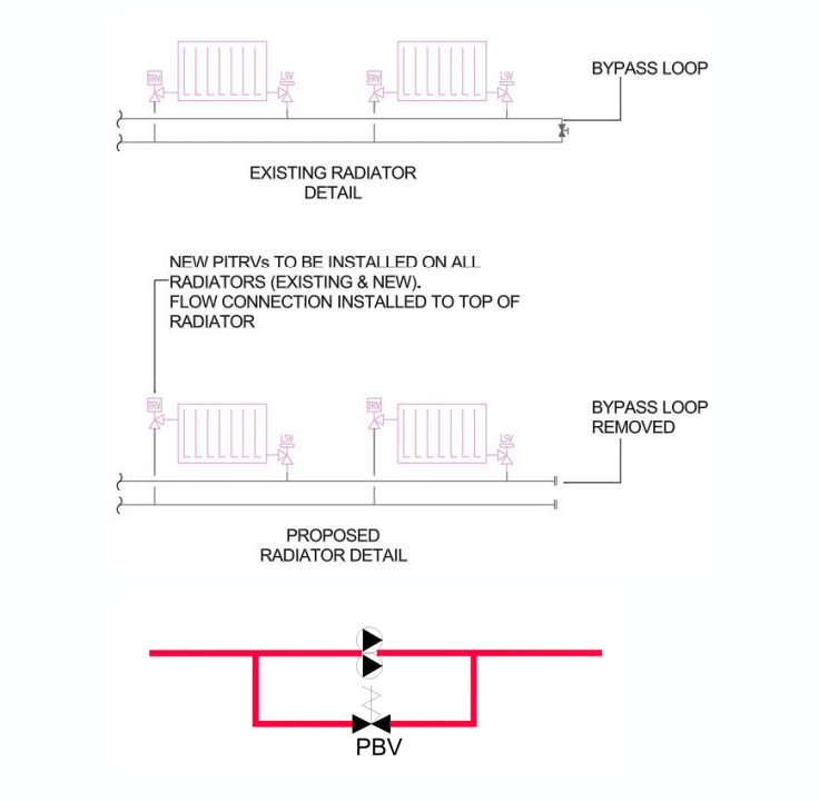
End-of-line bypass valves: the dos and don’ts
End-of-line bypass valves are typically installed to maintain minimum flow in a system, to ensure that pumps don’t operate under no-flow conditions.
In this way, they can also prevent pressure build-up when control valves in the system close.
However, when it comes to natural refrigerant heat pumps, it’s best to avoid or remove end-of-line bypass valves wherever possible.
This is because of the effect of unintended flow through the bypass.
Essentially, excessive flow can bypass heating zones, mixing warm flow water directly into the return line – and this can cause high return temperature.
So, what should be used instead?
Well, we usually advise using a low-flow bypass around pumps.
Low-flow pump bypasses should be installed with a pressure-balancing valve appropriately sized to accommodate the pump’s minimum flow rate and ensure proper operation at the valve’s opening pressure.
Let our expert system designers worry about emitter design for you
As you can see, there’s a lot to think about when it comes to emitter design.
And this stuff is mostly highly technical.
With that in mind, it’s worth noting that any technical advice provided here is for informational purposes only.
While we strive to ensure the accuracy and reliability of the information provided, it isn’t intended to be a substitute for professional advice or services tailored to specific circumstances.
Instead, our system designers can offer bespoke advice and guidance based on your unique circumstances – including your existing heating system, your building and your heat requirements.
They’ll take the time to understand your needs and to put together a complete commercial heat pump system design, tailored especially to you and your building – including the emitters!
So, what are you waiting for? Simply get in touch to start the ball rolling.
]]>